Large Format 3D Printer Cooling: Avoid Cracks on Long Prints
A crack at hour eleven of a twenty-hour build is the most expensive defect a large format machine can produce,
because everything printed before it is scrap. Most of the time it is not a nozzle fault or a bad file. It is heat leaving
the part on a schedule nobody chose. This is about large format 3d printer cooling as a controlled variable:
what your machine already offers, what it cannot do, and the order to change when a part splits.
A Crack Is Not a Warp
A warp and a crack look related on the shop floor and have almost nothing in common as defects. Warping shows
up early, at a corner or edge, as the part peels from the bed. A crack arrives late and often quietly: a hairline along
a layer line on the outer wall, a split through a thick section after the part has sat overnight. Ask why do big 3d prints
crack and the honest answer starts with timing, not a setting — which is why warping vs cracking comes first.
The second signal is direction. A bond that failed along a layer boundary is a thermal-history problem: the new
bead met a layer that had already given up its heat. A crack running across layers, through the middle of a wall,
is a stored-stress problem: the polymer contracted and something had to give. Both are cooling problems, fixed
in different places, so the observations come before the changes.
Where Heat Actually Leaves a Large Print
Three things pull heat out of a part on a big machine: the bed underneath it, the air around it, and the previous layer.
On a small part the three behave as one; past a metre they separate. The bed keeps the base soft; the air is the
variable you control, and the previous layer decides whether the bond is real.
A fourth path confuses buyers because the word is the same. Water cooling on our pellet machine serves the
extruder, not the print. The loop runs through the barrel so the feed section stays below the point where pellets
soften and bridge.
Nothing in that circuit touches the part. The only thing cooling the part on any of our machines is air and the bed.
Everything else the machine does with heat is about arrival, not removal. A nozzle runs hot enough to melt polymer
as the bead passes; a bed holds the base flat, and a cabinet slows how fast the air changes. None of that cools a part.
The gap between arrival and removal is where cracks are born, and that gap belongs to the air and the bed, not the
hot end.
Cooling Is Chosen Three Times, and Only One Is a Fan
The part cooling fan large prints need behaves nothing like the fan on a small machine. Air from one duct reaches
the top few millimetres and the near edge; across a bed measured in metres, the far side sees a fraction of it. A fan
percentage copied from a small printer does not carry over; the fan becomes a first-layer and surface tool, not a
whole-part control.
The control you do have sits in three places. The slicer sets fan behaviour layer by layer. The machine owns the air
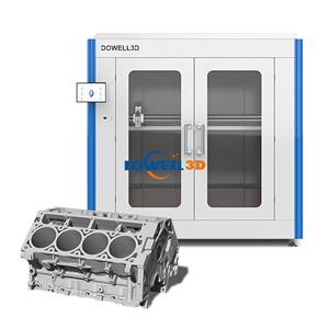
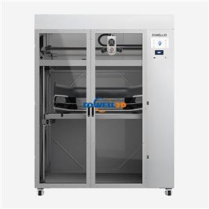
the part sits in, and where an enclosure rated 60°C is fitted, that air stops changing when the shop does; a bed
option reaching 150°C keeps the base warm through the hours the top takes to catch up. The rest belongs to the
building — a roller door, an extraction fan, a bay door down the aisle. Enclosure temperature stability matters less
than the absence of sudden change; a door left open for a delivery does more damage than a cabinet running a
little cooler.
The Long-Print Trap: Stress That Accumulates
Print cooling too fast is not a setting error you make once; on a long job it is a decision repeated thousands of times.
Every pass lays hot polymer onto cooler polymer, and each layer above reheats the one below by less as the stack
grows. When the layer bonding large parts depend on is weak, the record sits inside the part as a gradient from a
hot core to a fast-cooled skin — the source of the thermal stress large prints carry into service.
Then comes the section nobody watches. The job ends and the machine stops; the part then cools from bed
temperature to room air in the open. Thick sections hold heat longer than thin walls, so a 30 mm boss and the 6 mm
wall beside it contract on different clocks. That mismatch is the release event: cooling induced cracks usually
open hours after the print finishes, or days later under load. Slow cooling after printing is not a courtesy to the polymer;
it is the last process step, and skipping it throws away the build.
The Order That Works
Close the chamber before you change a single setting. A draught beats every other variable on a part this size,
and no machine feature compensates for an open door.
The air is the next decision, not the fan. Bring the cabinet to a steady temperature and hold the bed near the top
of its range for the polymer you run, so the base stays warm while the top catches up. Our standard bed reaches
100°C and the heated-bed option reaches 150°C. Either number works; holding it constant is what matters.
Then the fan, which keeps a narrower role here than on a small machine. Where a wall is wide and each layer follows
the last quickly, air is cooling polymer that needs to stay warm — cut it there. Narrow features near the top still
want the airflow for surface quality, so this is a decision per feature rather than per print.
Geometry comes after the air, and it is the cheapest lever. A thick unbroken wall is a heat reservoir wrapped in a
cold skin, so split it with ribs, pockets or curvature. Wall thickness settled at the drawing stage is a cooling decision
as much as a strength one.
Layer height moves the same way, only more slowly. Across the 0.04-0.6 mm range the printer offers, taller layers
mean fewer passes and less heat injected per unit of height, leaving a heavy section with less residual stress to
release.
Whatever the file specifies, the final hours decide the outcome. End the job inside the box: hold the cabinet and
let the part come down gradually, or at minimum keep the chamber shut until the bed reads near ambient.
Skipping it throws away the reasoning behind every step above.
Instrument the Build, Not Just the Print
Two things make cooling visible while there is still time to react. The temperature graph is the first: watch the
chamber and bed trace across the whole job rather than at the start, and look for a step change. That step is a
draught or a door, and it marks the hour the crack opened. Time-lapse from the camera is the other, turning a
vague overnight failure into an hour on the clock. Remote control matters for the same reason: whoever needs the
trace is rarely at the machine.
The Short Version
Large format 3d printer cooling is not a fan setting. It is the rate at which heat leaves the part over a build measured
in hours, set by the air around it, the bed under it, and the cool-down at the end. Fix the draughts, hold the chamber
steady, pull air off thick sections, and let the part come down inside the enclosure. The crack that opened hours into
the build stops being part of the plan.